 Welcome to
KF6ELU's Ham Radio Place!


**My latest radio and antenna projects as of April 19th - 30th, 2021.**
(Pic below here info)
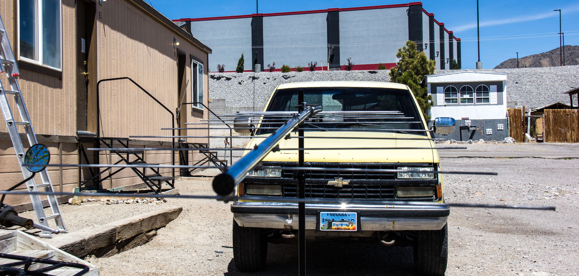
The project began in the radio room, making the radio table wider for radios and stuffs.. HiHi 
As of April 20th, 2021, I now have a Stryker 80-90 watt SSB/AM/FM radio for 10 meters! Of course, the band is totally dead for right now dayz. For right now, all I put up for antenna to it, is the old farmiliar Antron 99 verticle base antenna. They call is the Patiot 99 nowdays. It was a sombich getting it tuned for 10 meters too! Those 2 big nuts they use for tuning rings in the ground plane part of the antenna.. well.. its not a very wideband antenna thats for sure! I got it tuned at 28.400 with a 1.2-1.3 SWR. If I go any over or under .100 in that frequency range, SWRs go ape chit on it over 2.0 and higher. Am planning to get a 10 meter squalo loop horizontal polorized for it eventually. Oh well.. I am a SSB lover no matter what band I on!

(Pic below here info)
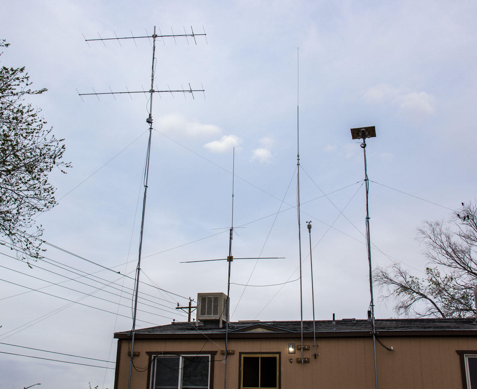
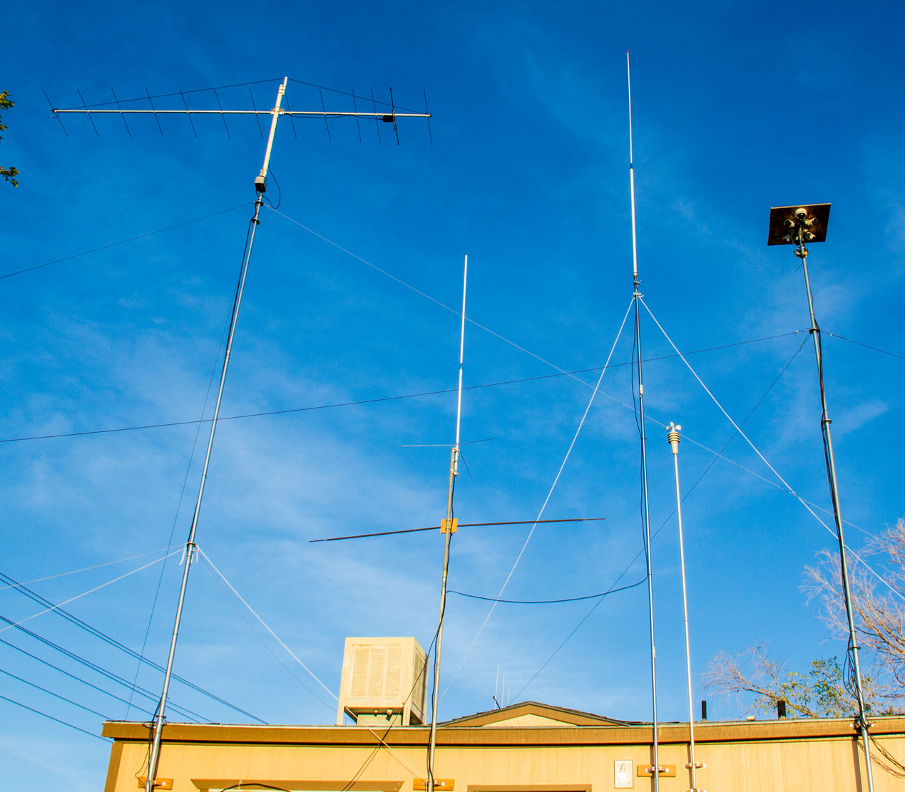
This particular pic I just recently took and updated April 23rd, 2021, after still gradually getting things setup. At this time, is a TRAM 2 mtr - 440 mtr dual band base antennna at my home. The ground
plane of the antenna is about 25ft up. It is to the right of the beam antennas. The deal in the middle-right is weather sensor about 20ft up. The taller one on right is my security cameras at 30ft. The one to the left of the weather sensor is a 10 meter antenna. The diapole just below the Tram base antenna, is a homebrew 6mtr I built and put up back in February 2021. Only tried it once, but it's there. Using it for 6mtr SSB, which is dead for nowdays. I did have 2 of the Cushcraft A-148-10T beam antennas up and operational at 40-50 feet as of March 19th, 2021 thru April 26th. Did not like the narrower beam pattern. They are down now, and put up a Cushcraft 13B2.
(Pic below here info)
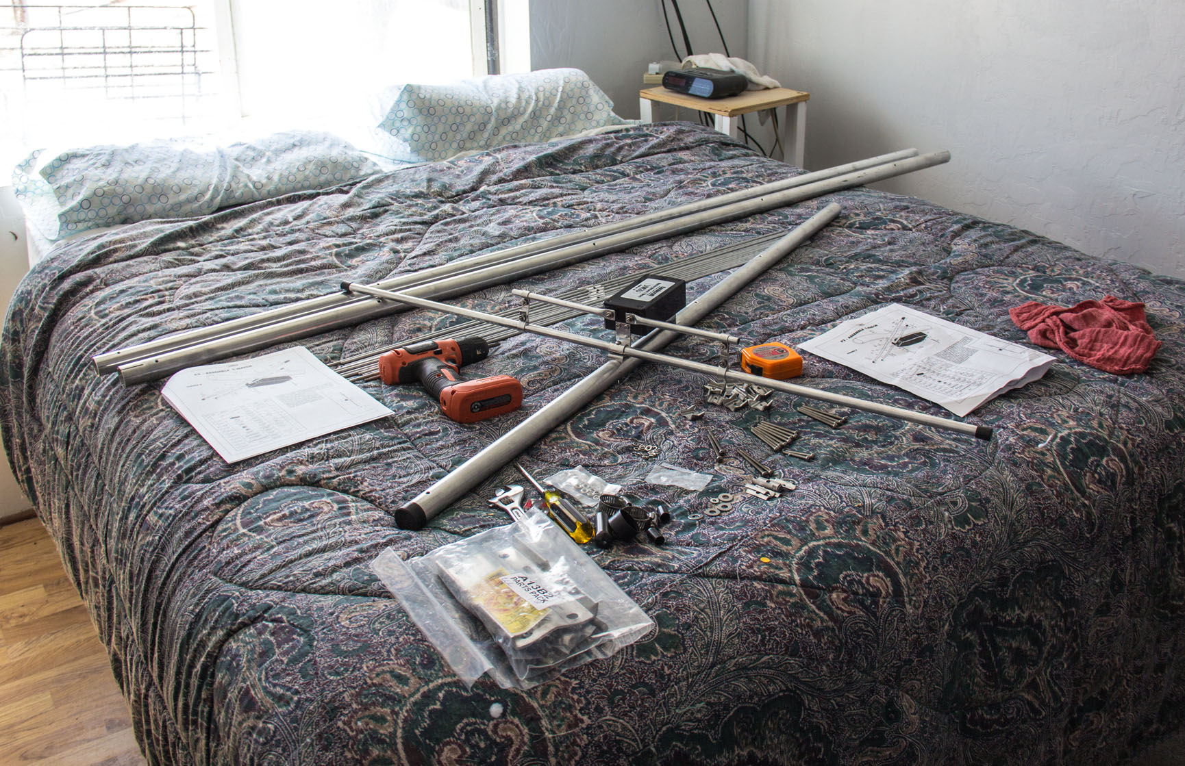
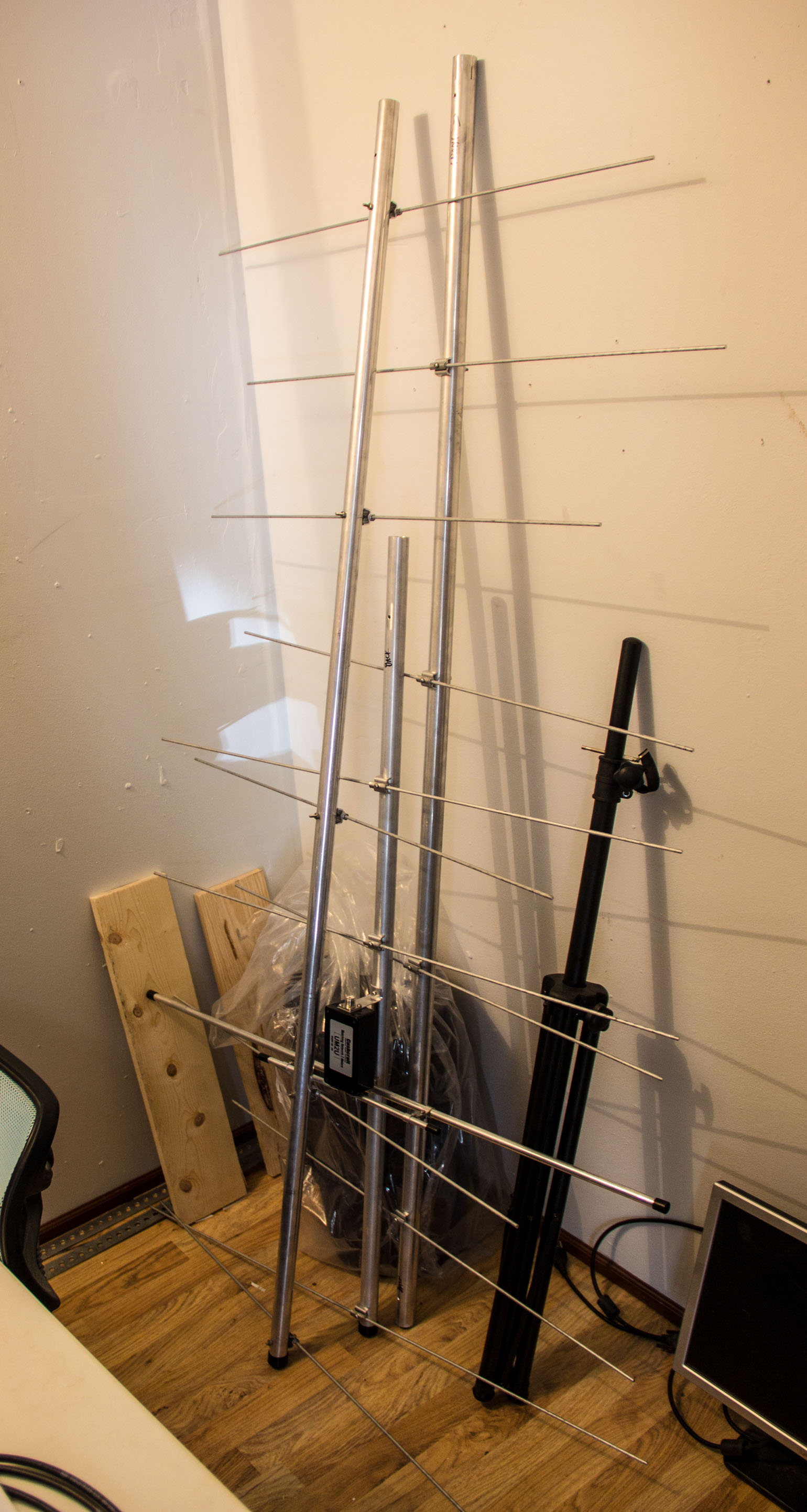
On April 19th, 2021, I started the 13B2 antenna assembly, of course, on my soft bed work bench. Assemble it in the 3 sections as usual. Was surprised to see that the 13B2 uses a T-Match for the input on driven element. Never had that before myself on a beam antenna. Having put the 2 10 elements beams together in the past, this one went a bit faster for me, knowing better what to expect.
(Pic below here info)
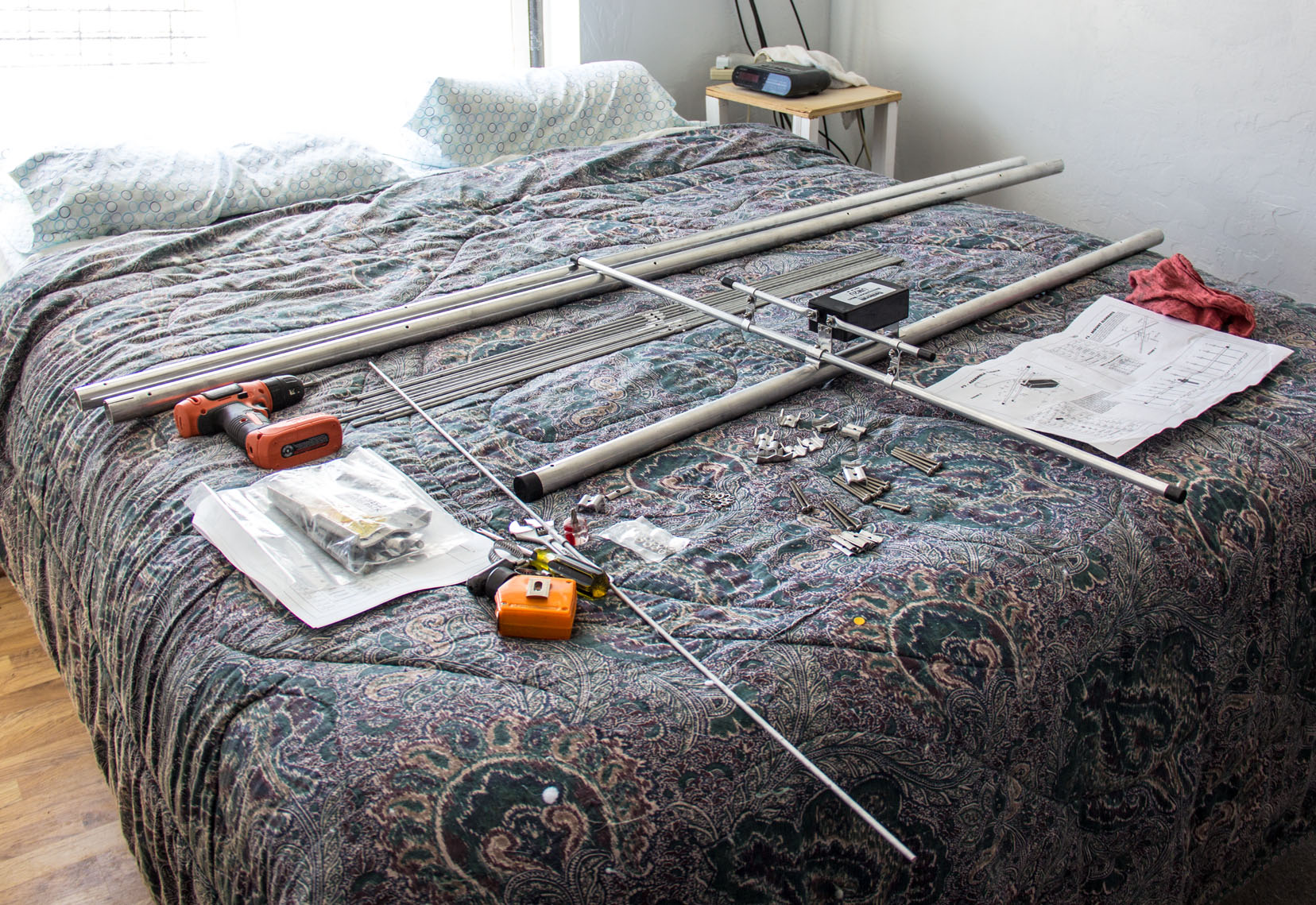
Gettin closer to the back driven section of the beam together. So far, not having to do any modifications to the factory's pre-assemble of it.
(Pic below here info)
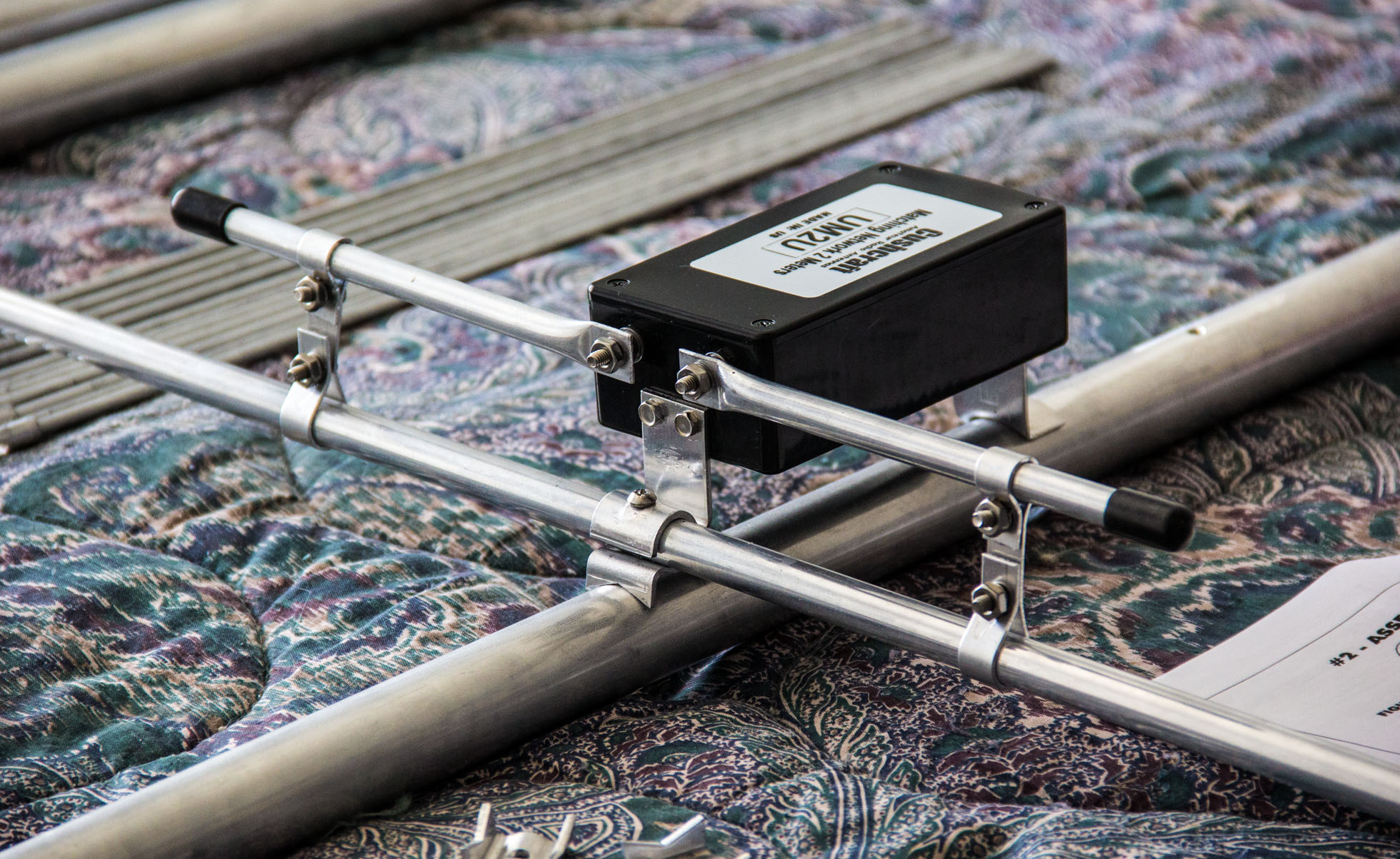
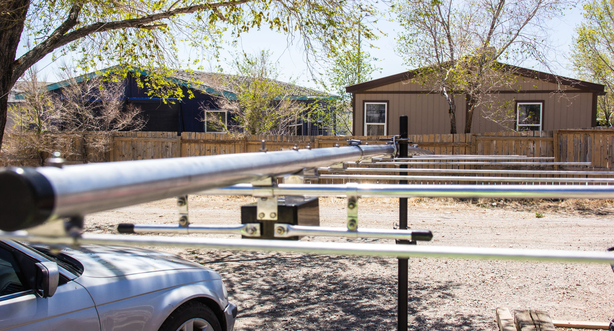
Close up view of the T-Match and driven element. Not hard at all to set up.
(Pic below here info)
This is all 3 of the sections put together. I did also get one of those MFJ tri-pod stands to use for assembly outside when the time comes.
(Pic below here info)
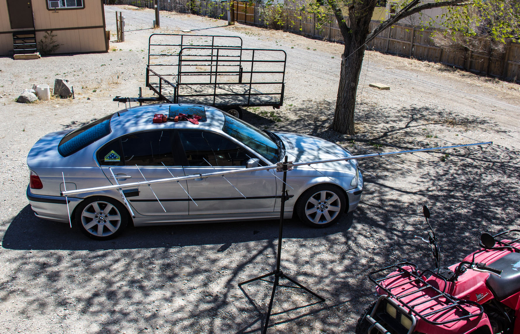
Using the tri-pod, which is great and much more easier to put the beam together, this is what it first looked like before doing final tweeks-n-skweeks to it, and the final SWR check and settings.
(Pic below here info)
Doing the look at how the beam may sag some or not, I did decide to put a suspender to it when the time comes of putting it up yonder in the air. I did notice that the back section to the mid section, is a little bit bigger diameter to it, therefore that straighter to it.
(Pic below here info)
Another angle view of the beam sag that is toward the front mainly, ahead of driven back section and the mid-mount section where the mast hooks up at. I do realize now, that having the tri-pod to assemble the beam, and do SWR check and other necessary observations, is a must for beam work and assembly. Helps big time before you actually get it way high up yonder!
(Pic below here info)
The view from front towards the back. Quite the sag to it. Did not measure what the sag-droop is, but this 13B2 does definitly need a suspender if anyone ever gets one.
(Pic below here info)
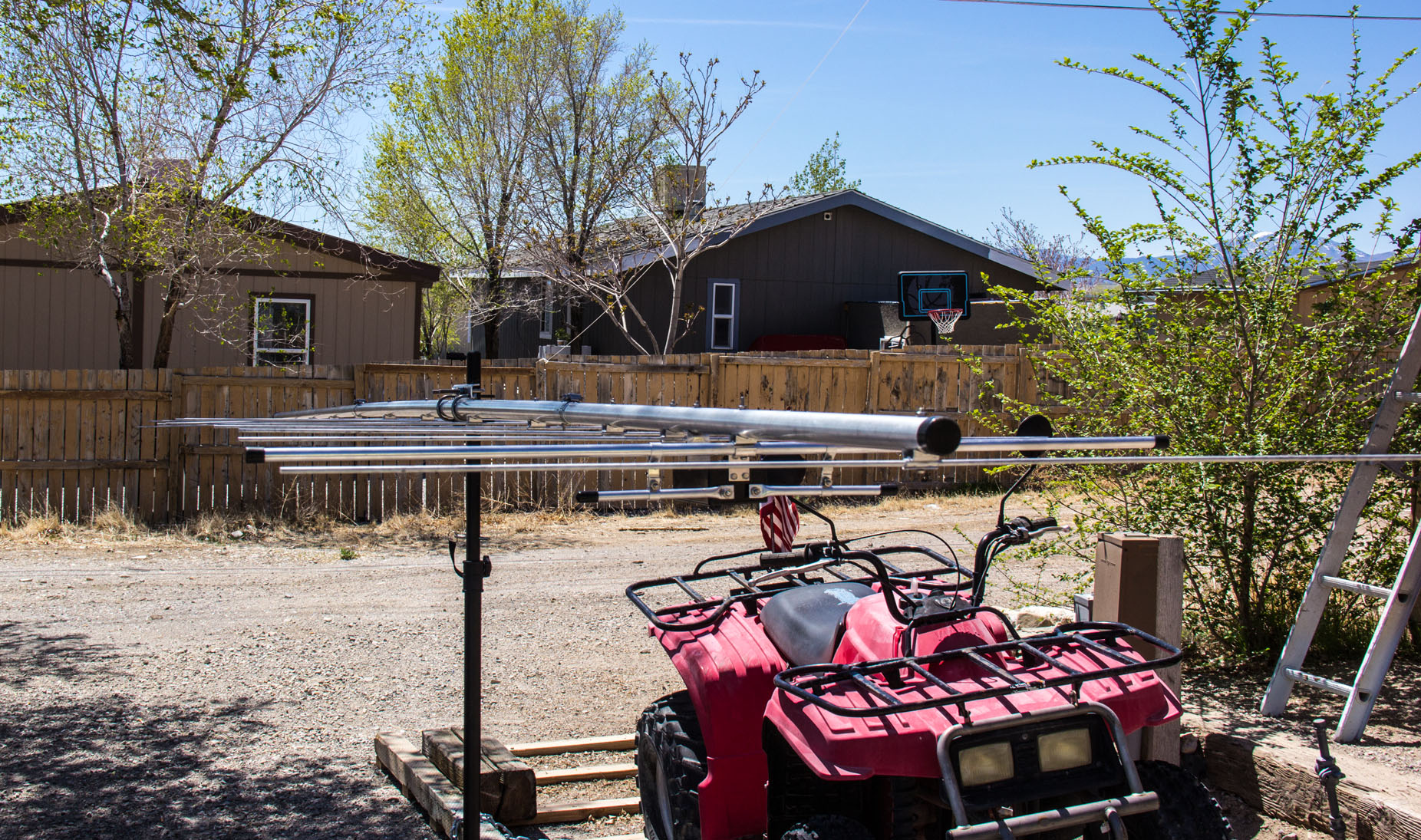
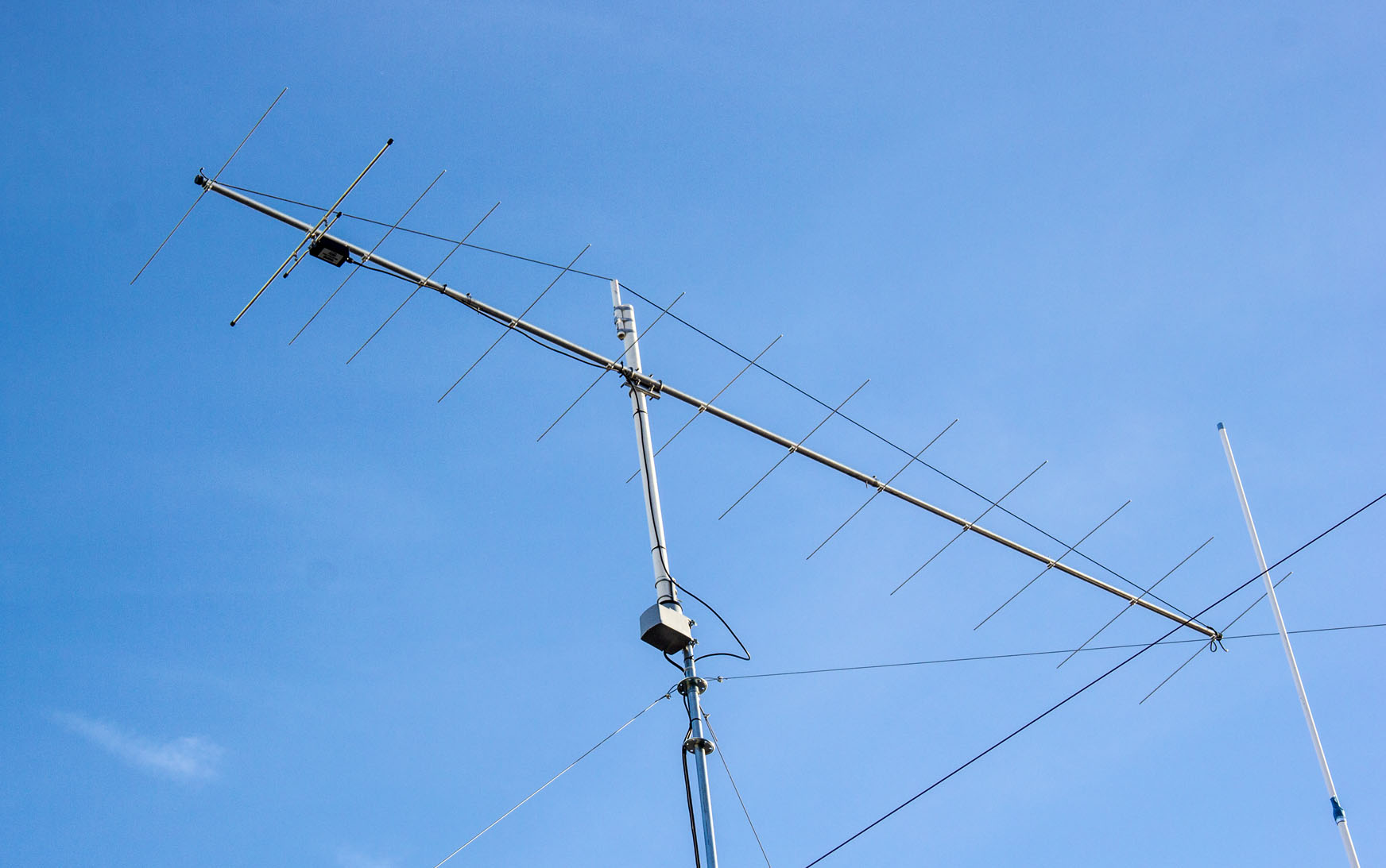
View of antenna once I got it up on the mast tower. It is back to operating at 40-45 feet. I made the antenna mast, out of 2 inch PVC pipe, with enough extension on the top with a smaller 3/4 inch piece that I notched to handle the para-cord that I used for the suspender.
(Pic below here info)
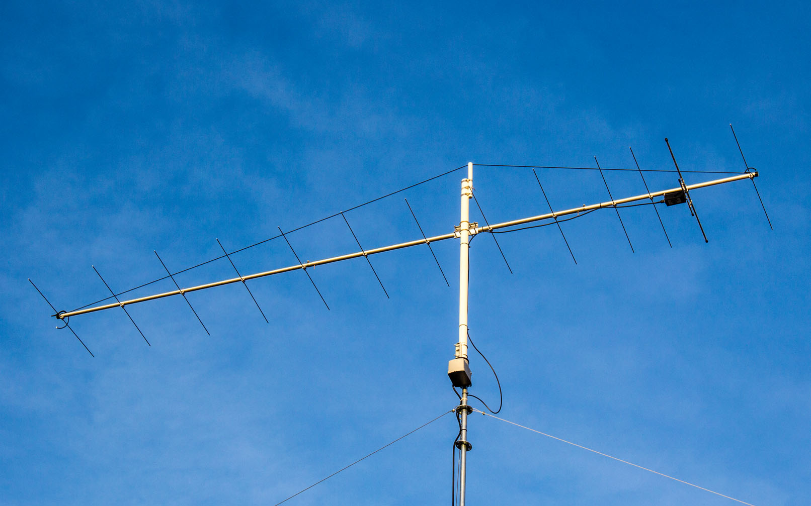
View of opposite side of antenna with it finally up in the air.
(Pic below here info)
This is what everything is looking like as of May 1st, 2021. The performance of the single 13 element beam, compared to the 2 10 element beams that I had stacked up there, soon to be announced.
 to go back to top of this webpage to go back to top of this webpage

© KF6ELU 1995-2024, All Rights Reserved ©
Website design © www.ias.cc
|
|
|